Based on the assessment of fault causes, it shows that power outages from the high voltage grid account for about 10%, the low voltage network 30% and the medium voltage grid account for 60%. Therefore, in addition to measures to improve the quality of operation management, the application of automation solutions on the medium-voltage grid is a very necessary requirement. This article deals with issues of investment and effective exploitation of automation functions on medium voltage grids, in order to reduce the time and scope of power outages due to breakdowns, contributing to improving the quality of electricity. power supply.
Currently, along with the application of remote control methods, solutions using Fault Passage Indicators (FPIs), effectively coordinate with devices. Automatic Reclosers (AR) and reasonable arrangement of automatic segmentation devices (Sectionalizer Automation) will be effective solutions with reasonable investment costs, helping to quickly detect breakdown, quickly restore power supply and limit the power failure range of the load.
Fault segment indication devices (FPIs)
Using fault segment indicator devices (FPIs) on medium-voltage grids is a low-cost, easy-to-install solution, quick assistance in identifying fault locations on long lines. . The determination of the location of installation of FPIs on the grid is calculated on the basis of the short-circuit parameters of the grid as well as the convenience of fault segmentation operations. When short-circuit currents are detected in combination with voltage loss logic, FPIs will issue an alarm signal for the operator to quickly assess the extent of the fault. The principle of fault segmentation based on device FPIs is depicted in the figure below.
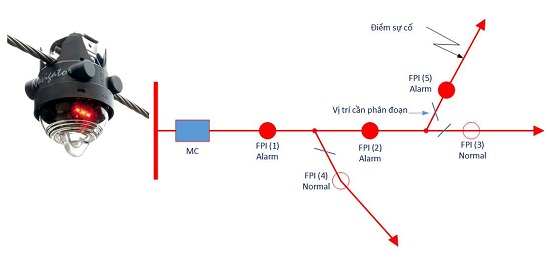
Figure 1: FPIs . device-based fault segmentation principle
In the fault situation described in the diagram above, the feeder circuit breaker operates, directing the short-circuit current power, causing the fault segment indicator devices FPI(1), FPI(2), FPI(5) to emit alarm signal (Alarm), FPI(3), FPI(4) devices are in normal state (Normal). Depending on the monitoring function of the FPIs, the alarm state of the device is reset automatically when the voltage is restored (used to detect maintenance problems, failed re-close breaker) or The device is reset manually (used to detect transient failures when the feeder breaker closes successfully). Based on the alarm signal FPIs, the operator will quickly locate the correct fault segment.
Depending on the characteristics of the medium-voltage grid, FPIs are made to work on the “power grid” in the air or on the underground cable network, according to the working mode of the system neutral. In addition, FPIs devices have the ability to detect current direction by combining voltage sensors with current sensors, these devices are mainly applied to interchangeable loop-linked power grids. power direction change.
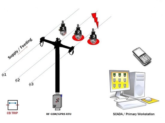
Figure 2: Solution for remote monitoring of FPIs . devices
With the requirement of remote monitoring of the fault warning mode on the power grid, improving the accuracy of the fault location function on the SCADA/DMS system, FPIs are easily connected to the RTU supports RF signal transceiver function within 10 – 20m, Alarm signal from FPIs is sent by RTU to the center by transmission lines via common GSM/GPRS service. When a fault is detected, the RTU from the fault location sends an event message in the form of an SMS message with a predefined syntax, the control system or the operator receiving the message will quickly determine the range. faults on the power grid.
Automatic Recloser (AR) device
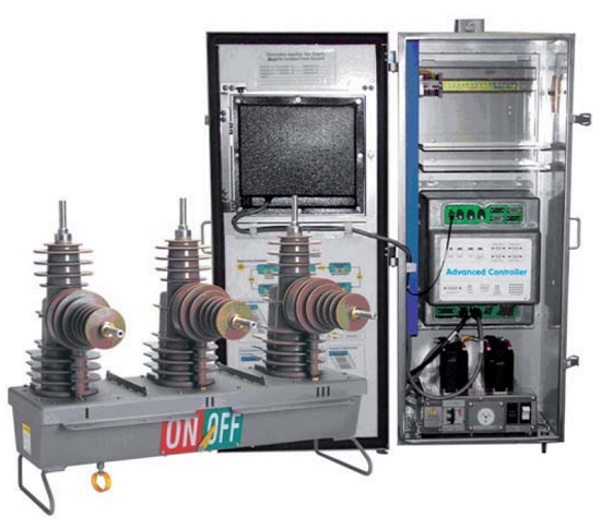
Figure 3: Automatic Recloser (Automatic Recloser)
Installing automatic repeater closing (AR) equipment on medium-voltage power grids is the preferred solution to eliminate transient fault situations (with a probability of over 70%), and at the same time convenient in connection methods. remote control connection. However, the optimal setting of the automation functions of the AR equipment will increase the effectiveness of the protection methods on the grid.
The setting of the relay protection parameters of the equipment must be generally agreed upon in the relay protection strategy of the power system. In which, the protection coordination method of the ARs on the line is coordinated sequentially (Coordination Sequence) with other protective devices on the power grid, specifically the coordination options should be noted as follows:
– Coordinate AR with source-side FCO
– AR coordination with load-side FCO
– AR coordination with feeder protection relay
– Coordinate AR with other ARs
The AR now supports a lot of functions protection. Depending on the relay protection strategy on the grid to exploit the protection functions of AR appropriately and effectively. For basic protection functions such as phase overcurrent protection (F50/51), earth fault overcurrent protection (F50N/51N), from the grid short circuit calculation parameters, uniformly applied current-time characteristics according to IEC 60255 or ANSI/IEEE C37.112, ensuring protection coordination requirements. Some advanced protection functions of AR such as reverse sequence current protection (Negative Phase Sequence – F46), directional over current protection (F67), undervoltage protection (F27) and current protection Sensitive Earth Fault (SEF)… need to specifically evaluate the nature of the power grid and its ability to coordinate with other devices to ensure selectivity in the protection method. On the basis of the working modes of the power grid, setting appropriate protection groups, some ARs are capable of assessing the load current and power direction to automatically select the appropriate protection group. in accordance with the operating mode.
Besides, it is necessary to base on the characteristics and nature of the load to use other supporting functions such as cold load compensation function (Cold Load Pickup), anti-starting function (Inrush Restraint Current). These functions are capable of automatically assessing the load to adjust the relay protection characteristics of the equipment in the event that the equipment is closed. However, automatic adjustment of the relay protection characteristics must be carefully considered in the protection coordination methods of the system.
The auto-reclosing function is very effective in cases of transient failures. Depending on the characteristics of the power grid to set the number of cycles, the waiting time (Dead Time) and the recovery time (Reclaim Time) of the closing cycle accordingly. Most AR devices support more than four repeat closes in a cycle, but the probability of successful closing is concentrated on the first two times with a closing time of 1-30 seconds. The recovery time of the re-close cycle must be large enough (over 180 seconds) to prevent continuous operation of the equipment in the event of a short-term fault on the power grid. Limit the use of auto-repeat function in the case of AR equipment protecting underground cables or protecting power transformers, because failures on these protective objects are often sustained failures. The repeat close function must also be considered in the case of coordination with other devices as well as coordination with automatic fault segmentation devices to achieve the best results in automatically restoring the power grid.
Loop Automation (LA) is supported by AR devices on grids with ring links. Based on voltage and current sensors and the ability to assess power direction, when there is a fault at a point on the ring-linked grid, the ARs will isolate the fault area and automatically restore power to the network. the loads are outside the affected area of the fault. The above process is done automatically based on simple time coordination logic algorithm, the devices have absolutely no communication connection.
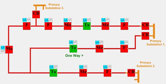
Figure 4: Diagram depicting automatic loop closing function of AR .s
According to the above grid diagram, ARs are classified by installation location: Output (Feeder – F), Segment (MidPoint AR – Ma), Normally Open (Ray AR-Ta). In the event of an incident in the range between two ARs acting as segment (Ma) and feeder (F), or feeder (F) and source breaker (CB), the Ma-type ARs will automatically open after when source side voltage loss is detected, AR type Ta will check voltage loss condition to one side, after a safe established time period, AR Ta will automatically re-energize the sub-scope power supply load between two ARs of type Ma and Ta. This is a simple solution in automatically restoring the power grid, but the automatic loop closure (LA) function only works correctly with a stable grid structure and invested control protection devices. synchronized.
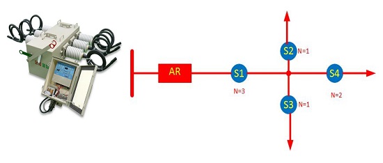
Figure 5: Diagram illustrating the coordination method between recloser and SA . devices
Recloser and automatic device for fault segmentation (Sectionalisers Automation (SA)
A typical fault segmentation device is a load disconnector (LBS) with a controller capable of monitoring mains voltage, counting the number of power outages in a certain period of time to automatically perform cut LBS. According to the diagram illustrating the coordination method between the recloser and the SA devices, the feeder AR device is set to three repeat closes. Depending on the priority nature of the load and the operating characteristics of the grid, SA devices are installed to operate accordingly after the repeated closing (N) of the AR. In the above case, device S2, S3 will operate after the first re-close, device S4 operates after the second re-close, device S1 operates after the third re-close. The logic of sequential coordination between the AR equipment and the SAs will ensure quick restoration of power to priority loads, while easily identifying the extent of faults on the grid. In addition, SA devices also have the ability to connect to the central control system, supporting remote control operations to segment incidents.
Conclude
The requirement to improve the reliability of power supply by reducing the time and scope of power outages due to incidents requires the application of many synchronous measures, from operation management to the application of automatic solutions. automation for the power grid. Effectively exploiting the automation functions of equipment on the power grid is an effective and economic solution. However, in practice, the applicability of the above solutions depends heavily on the synchronization of the grid structure, as well as the user’s ability to manage and operate equipment. This is also an orientation in the smart grid development strategy (Smart Grid) that EVN is building.
(Source: hiendaihoa.com)